
Part 5: Failure Mode Testing#
No project is complete without theorizing different failure scenarios and then testing them. Sometimes things behave as I expect, sometimes they do not. In the cases where they do not, I either learn something about a constraint, or find a flaw that can be fixed.
Failure Case 1 – Single Cluster node failure#
Let’s look at the case where a single Cluster member fails. Recall there are two Clusters, one in each AWS Region. Each regional Cluster has two nodes, and in steady state, roughly half of the Edges assigned to a Hub Cluster will land on vce1 and half on vce2 for reach regional Cluster.
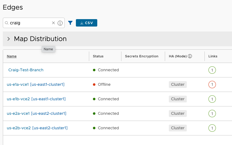
I’m only working with a single test branch Edge, and the VCO shows me which Cluster node it is currently assigned to with the gray Cluster label indicator.
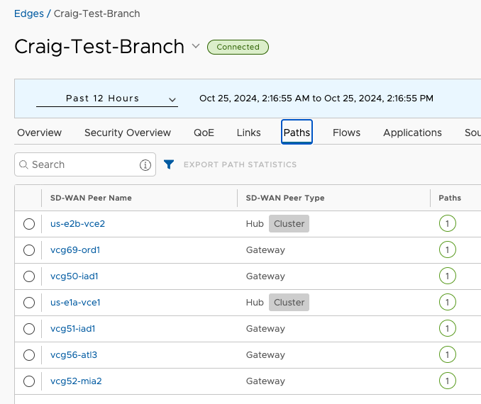
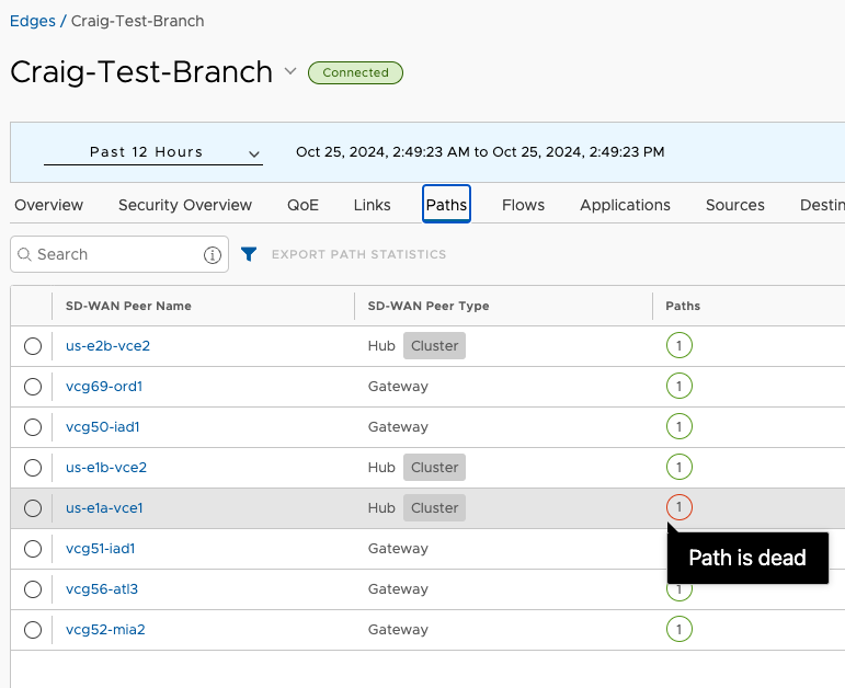
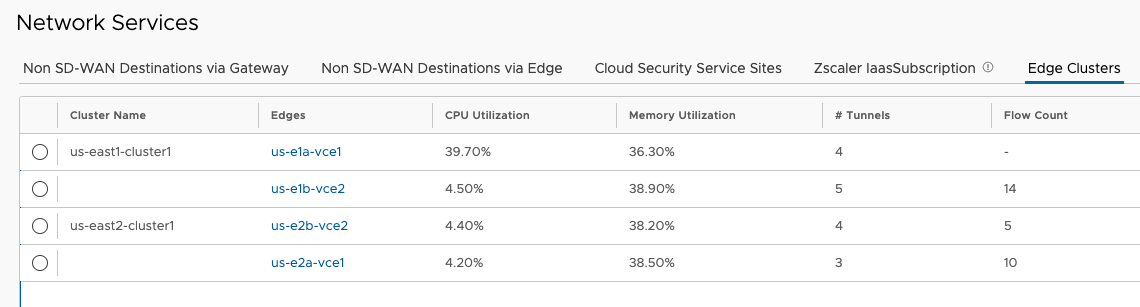
The VCO has steered Craig-Test-Branch to node us-e1a-vce1 of the us-east1-cluster1 Cluster and us-e2b-vce2 of the us-east2-cluster1 Cluster. So logically I’ve got this:
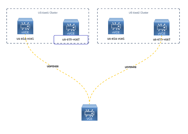
Looking at vtysh on us-e1a-vce1, I can see it is indeed advertising my Branch prefix 192.168.111.0/24 to both of its peers to TGW
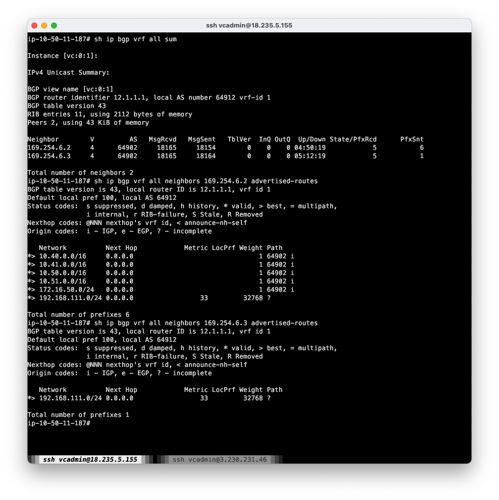
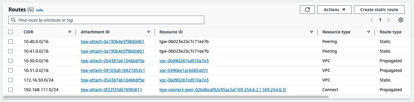
And the TGW is receiving it
Failure#
Now I start a ping to a test workload in the us-east1 Compute VPC and then abruptly shut down the us-e1a-vce1 instance.
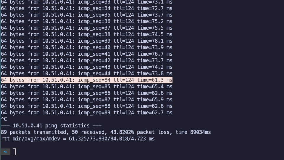
You can see the sequence skip from 44 to 84, indicating about 40s for the test Branch to get reassigned to us-e1b-vce2, that node to inject the Branch prefix, and for BGP to converge inside of AWS.
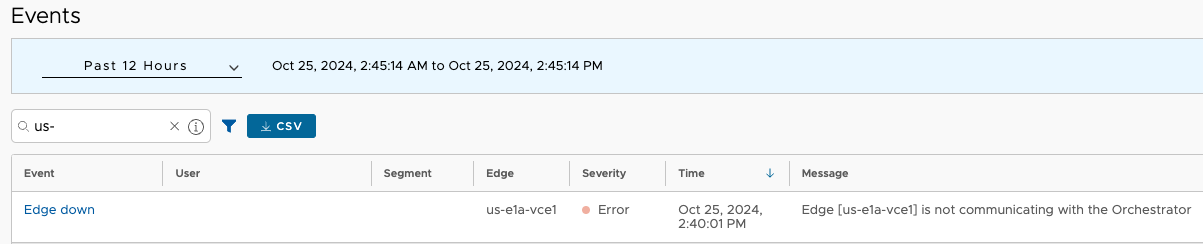
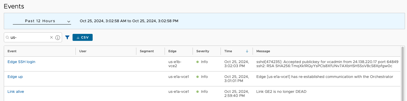
VCO noticed and evented that us-e1a-vce1 went offline.
Restoration#
Now I restart the failed node. It should rejoin the Cluster, but no automatic pre-emption should happen as far as Edge assignments, and things should stay as they are.
Outcome: Acceptable#
This is the expected and perfectly outcome. If a Cluster loses a single node, the Edges which had been assigned to it will be reassigned to surviving nodes. The duration of completely automatic recovery from this rather significant fault was about 40s. I should repeat this for all nodes in all Clusters to be sure they behave similarly. The only caveat to keep in mind is not to exceed scale limits for a single Cluster node.
Failure Case 2 – Complete regional Cluster failure#
Now consider the case where all nodes of a regional Cluster fail. The expected outcome here is that all AWS prefixes from the Region where the Cluster fails will be lost. This is a fairly extreme failure scenario which could be brought on by both AZs failing, or more likely, a mistake made in AWS or VCO that affected that whole Cluster.
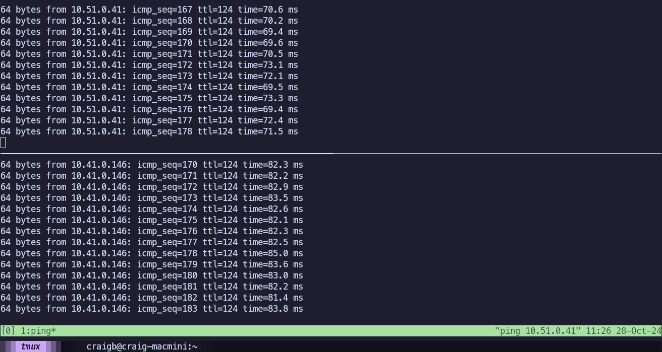
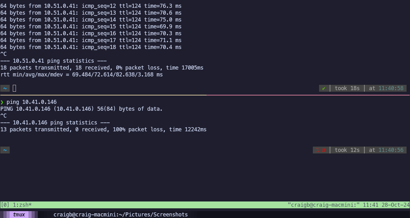
I start in steady state, able to ping the test workloads in us-east1 (10.51.0.146) and us-east2 (10.41.0.146) Compute VPCs from a workstation (192.168.111.24) behind my test Branch.
The OFC shows how these are reachable.
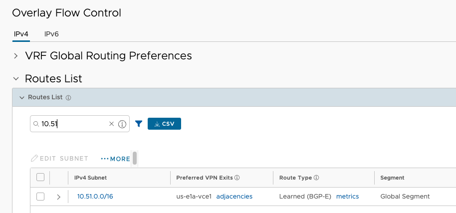
As expected, the traffic ingresses the us-e1 cluster to reach 10.51.0.0/16.
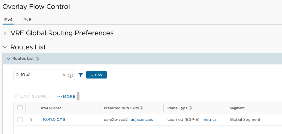
And the traffic ingresses the us-e2 cluster to reach 10.41.0.0/16.
Failure#
This time, I shut down both us-e2a-vce1 and us-e2b-vce2. This cuts off prefixes in US-East2 completely, but leaves those in US-East1 available. With that entire Cluster down, the test Branch is no longer able to reach 10.41.0.146 but 10.51.0.41 is still reachable.
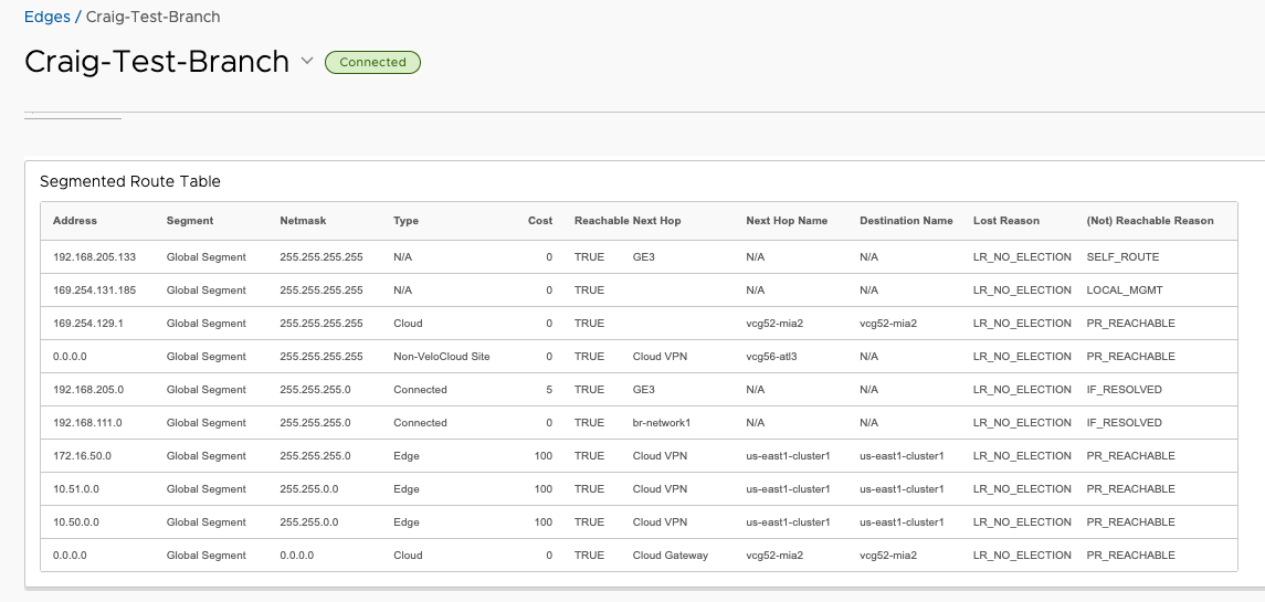
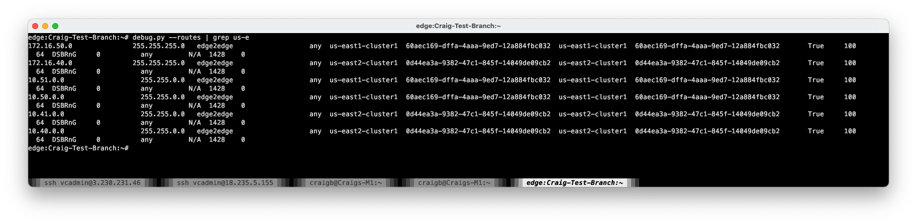
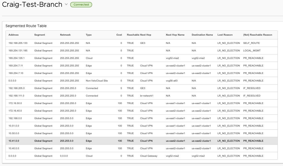
This time, I’ll look from the perspective of the routing table of the test Branch Edge from VCO and confirm that 10.41.0.0/16 is no longer available.
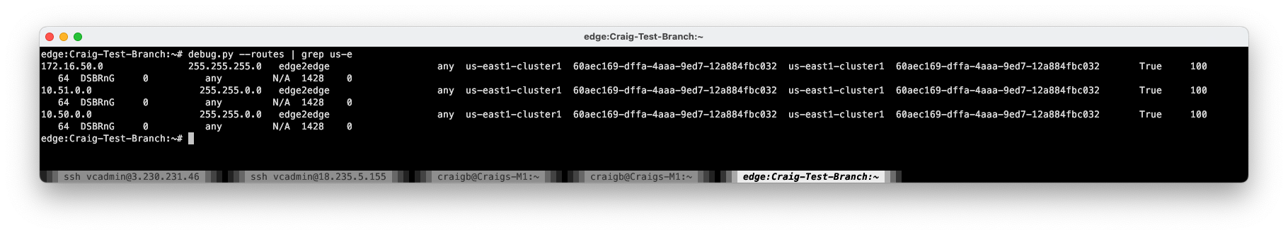
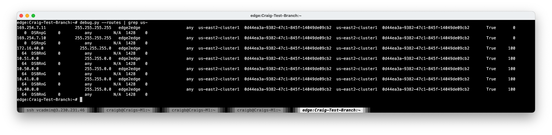
A look from the test Edge CLI confirms no routes at all to the us-east2 cluster.
Restoration#
After reenabling the us-east2 Cluster nodes, 10.41.0.0/16 is once again reachable.
Outcome: Acceptable#
This failure mode behaved as expected. The downside of a complete regional Cluster failure is that all workloads in the Region of failure become unreachable. But we can do better.
Improvement#
With a bit more work, this design can survive a complete Cluster failure in one of the two Regions.
TGW Peering#
TGW Peering provides an interconnect between the TGWs in the two Regions, and supports static routes. This is simple to add, and can be done from either of the TGWs that will participate. I chose to initiate the peer from us-east1-tgw, so I just needed to fetch and provide the ID from the us-east2-tgw.
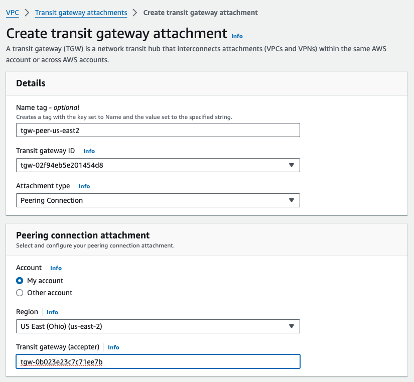
This request will go into a Pending Acceptance state, and simply needs to be accepted from the far side TGW.
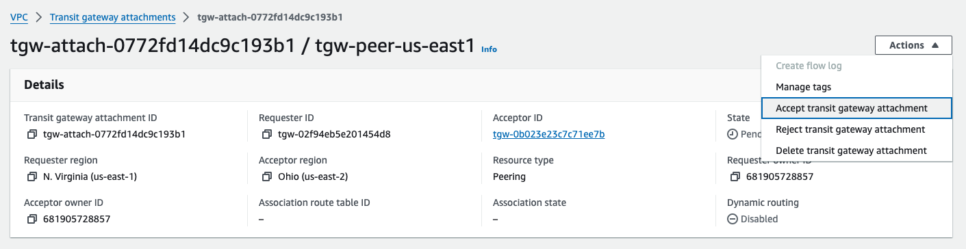
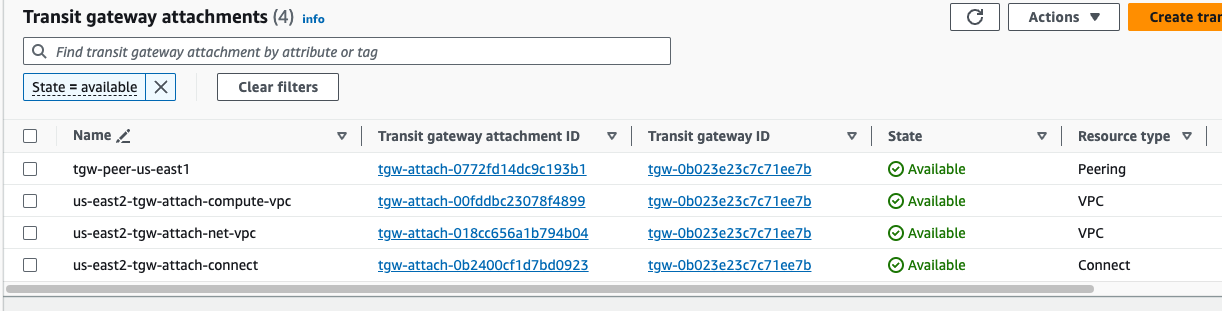
After a few minutes, the Peering shows Available on both TGWs.
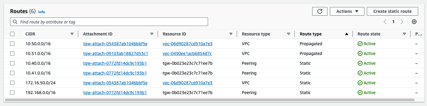
The TGWs will not initially share any routing information across this peering, and any desired routes must be added statically. Adding summary routes from each TGW routing table to the prefixes in the opposite Regions Compute VPC establishes a pathway between them.
Having a look a the OFC in VCO, I can see the /16s from each Region, just as expected, but with one twist. Before the TGW Peering and static routes were added, the Regional prefixes were localized to their corresponding Regional Cluster for Preferred VPN Exits.
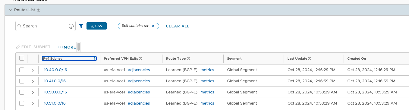
Now all four prefixes Perferred VPN exit is the us-east1-cluster1 (specifically us-e1a-vce1 node). This is functional and even desired for 10.50.0.0/16 and 10.51.0.0/16, but it means that traffic to 10.40.0.0/16 and 10.41.0.0/16 is now crossing between Regions, incurring fees. The reason for this is Velocloud VCRP’s best path logic. In this case, since these prefixes look equivalent as they are advertised from both TGWs to the Hub Cluster nodes, the tie breaker becomes Hub order. us-east1-cluster1 is specified first in the test branches Hub Order, so that Cluster is elected as the ingress for all AWS prefixes.
This is more clear to see in the metrics detail of Route Types.
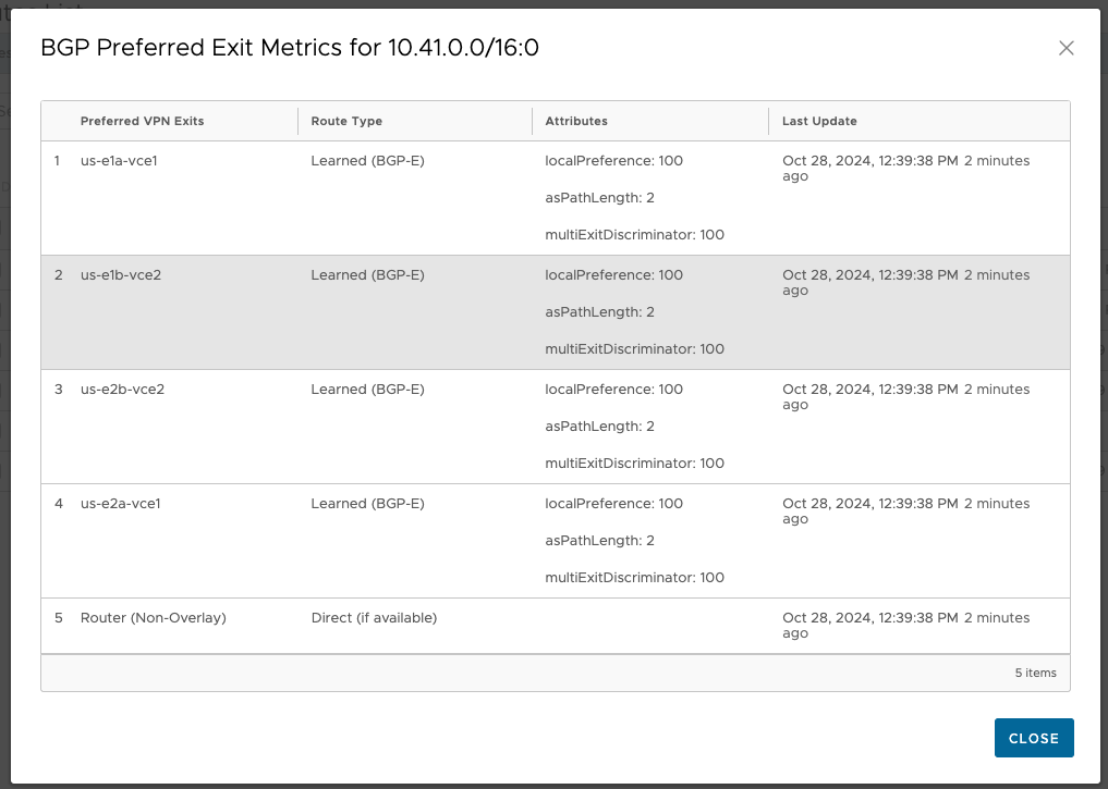
The good news is, the OFC is tunable on a per-prefix basis. So I make a small change on the Hub Order, to influence the ingress for these AWS prefixes. I only need to adjust those prefixes that live in us-east2 since us-east1 is already the natural winner for its own prefixes.
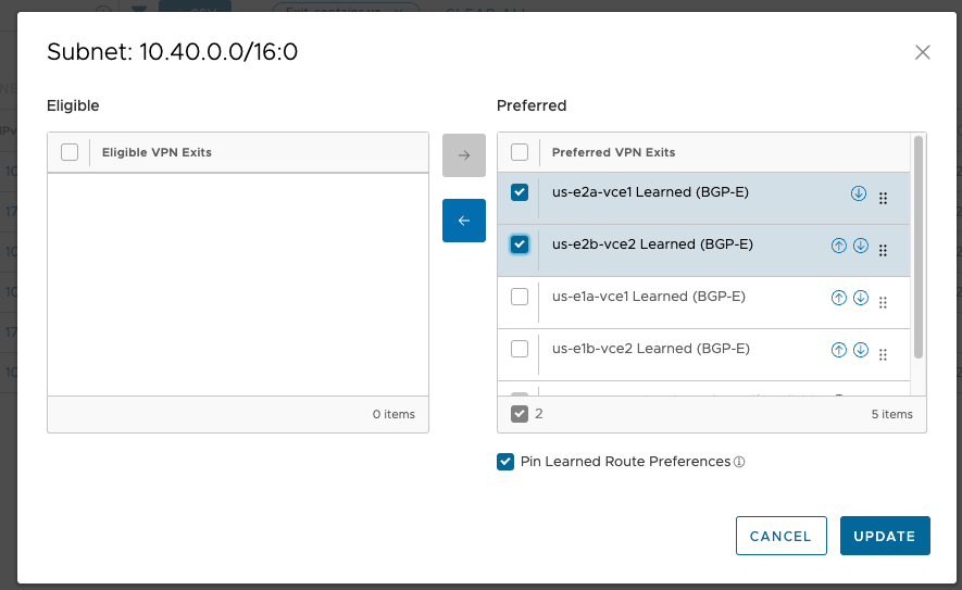
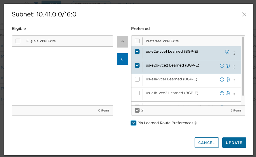
This is the behavior I’m looking for. The pushpin icon confirms that the change will persist across changes to the OFC.
Failure Case 3 – Complete regional Cluster failure revisited#
With those improvements, I’ll test failing a whole Regional Cluster again, this time failing us-east1-cluster1.
Failure#
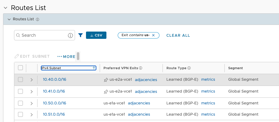
The Test Branch routing table looks good, having moved all prefixes to us-east2-cluster1 for ingress.
However, I still can’t reach 10.51.0.41. This is, of course, because I’ve not dealt with the return routing. Right now, the test Branch ingresses us-east2-cluster1, crosses the TGW peering connection, and has no return route in the us-east1-tgw routing table. Notice that 192.168.111.0/24 is not present.
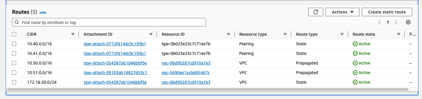
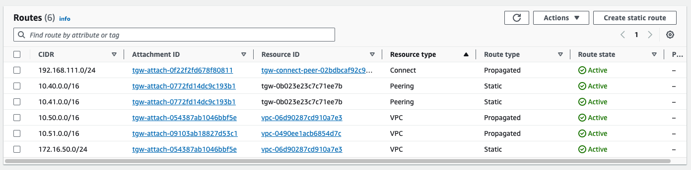
us-east1-tgw route table
Small Adjustment#
It is not being learned dynamically from us-east1-cluster1 (because it’s down), and there is no route across the TGW peering, because there is no static for it. I quickly add a static aggregate (less specific) route to both TGWs, pointing at the other, and my ping top 10.51.0.41 resumes, flowing in and out of us-east2-cluster1.
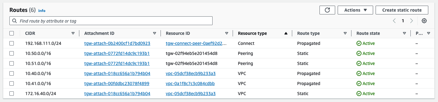
us-east1-tgw route table after adding static aggregate
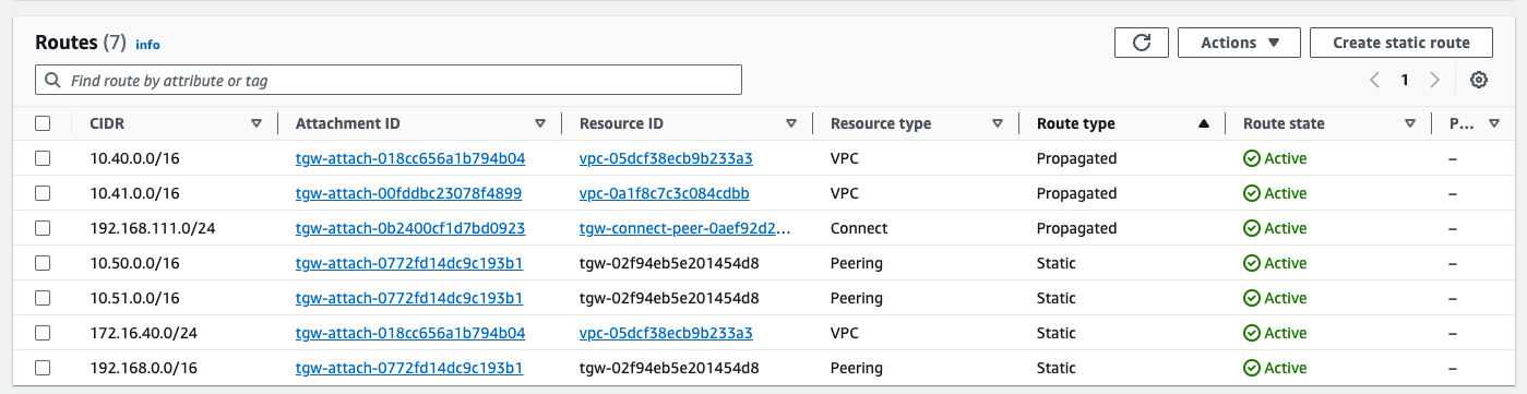
us-east2-tgw route table, with more specific being followed over the static aggregate
Restoration#
I start us-east1-cluster1 nodes back up to validate restoration. After a few minutes booting and reestablishing BGP peers with the TGW, the test Branch routing table looks great.
Outcome: Improved#
With those changes, now an entire Regional Cluster can be lost without isolating the Compute VPC in either Region. Nice improvement with minimal effort.
Part 5 Wrap Up#
Part 5 is a wrap and there were some good lessons learned in that failure testing. Let me know in a comment if there are other test cases you’d like to see.